AL-KO HYDRO-OPT® – Efficient Heat and Cooling Recovery in Run‑Around Coil Systems
The AL‑KO HYDRO‑OPT® series of hydraulic stations delivers reliable, energy‑efficient heat transfer within a run‑around coil system. A water‑glycol mixture circulates between the exhaust and supply air coils to transport thermal energy, achieving heat transfer efficiencies of up to 80%. A run‑around heat recovery system offers maximum spatial flexibility, as supply and exhaust air units can be positioned independently throughout the building. This makes it an ideal solution wherever system separation is required due to architectural constraints. In hygiene‑critical environments – such as healthcare facilities, laboratories, and cleanrooms – a run-around coil system is often the only technically and hygienically compliant method for recovering heat or cooling. With AL‑KO HYDRO‑OPT®, all components of the heat recovery system are perfectly coordinated to ensure outstanding energy efficiency, operational reliability, and long‑term economic performance.
Receive consultation in person
Run-around coil system: Advantages, Function, and Installation – Key Information at a Glance
How does a run‑around heat recovery system work?
When supply and exhaust air must be routed separately within a building, a run‑around coil system provides an ideal solution for heat recovery in central air‑handling systems. The AL‑KO HYDRO‑OPT® hydraulic stations combine high‑performance heat exchangers, advanced control technology, and all required system components into a perfectly matched run‑around heat recovery system with heat transfer efficiencies of up to 80%. This approach ensures strong planning reliability, enables energy‑efficient HVAC system architectures, and supports smooth installation and commissioning by qualified AL‑KO service specialists.
Advantages
- Makes a significant contribution to energy savings and sustainably reduces operating costs
- Optimized performance through dynamic, self-regulating volume‑flow control for maximum efficiency
- High heat transfer efficiency with temperature effectiveness up to µt ≤ 80%
- Compact design for flexible integration into various air‑handling systems
- Option to fully decouple the cooling and ventilation system with a single action
- Preconfigured electrical and hydraulic connections (excluding air‑side sensors)
- Remote access via AL‑KO REMOTE CONTROL for convenient monitoring and service available
Installation
- Professional commissioning and support provided by qualified AL‑KO service specialists
- Fast, secure installation thanks to preconfigured electrical and hydraulic connections
- Pre‑piped heat exchangers inside the unit reduce installation time and overall project costs
Run-around coil system: Functional Units and Technical Components
We offer a broad range of functions, functional units, and technical components – fully tested and perfectly coordinated to work together. The result is a high‑performance run‑around heat recovery system that ensures maximum energy efficiency, reliability, and planning certainty for central HVAC applications.
Hydraulic station AL‑KO HYDRO‑OPT®: Functional Overview and Technical Data
Function Overview – HYDRO-OPT S and HYDRO-OPT M at a Glance
| Function Description | HYDRO-OPT S | HYDRO-OPT M |
|---|---|---|
| Number of supply air units 1.9 m3/h | 1 | 1 |
| Number of exhaust air units 4.9 m3/h | 1 | 3 |
| Intelligent pressure-independent control of multiple exhaust air units | ✓ | |
| Control cabinet with controller and inverter | ✓ | |
| Control integrated in the inverter | ✓ | |
| Main switch | ✓ | ✓ |
| Power control with pump + valve | ✓ | ✓ |
| Air volume-dependent power control | Control via external regulation is possible | Used by intelligent DeltaT control implemented |
| Release signal | ✓ | ✓ |
| Fault signal | ✓ | ✓ |
| Control 0–-10 V | ✓ | ✓ |
| System pressure monitoring warning | ✓ | |
| System pressure monitoring shutdown | ✓ | ✓ |
| Frost protection control | ✓ | ✓ |
| Circulation increase | ✓ | ✓ |
| Bypass valve | ✓ | ✓ |
| Bus connection BACnet IP | Optional | |
| Bus connection BACnet MSTP | Optional | Optional |
| Bus connection Modbus RTU | Integrated | Integrated |
| Bus connection Modbus IP | Optional | |
| Controllable pump | ✓ | ✓ |
| Double pump | ✓ | |
| Pump blockage protection | ✓ | |
| Pump vent valve | ✓ | ✓ |
| Display of supply temperature | ✓ | ✓ |
| Display of return temperature | ✓ | ✓ |
| Flow meter | Mechanical display integrated | Electrical display on the display |
| Manometer | ✓ | ✓ |
| Expansion vessel and safety valve | ✓ | ✓ |
| Filling and draining device | ✓ | ✓ |
| Dirt trap | ✓ |
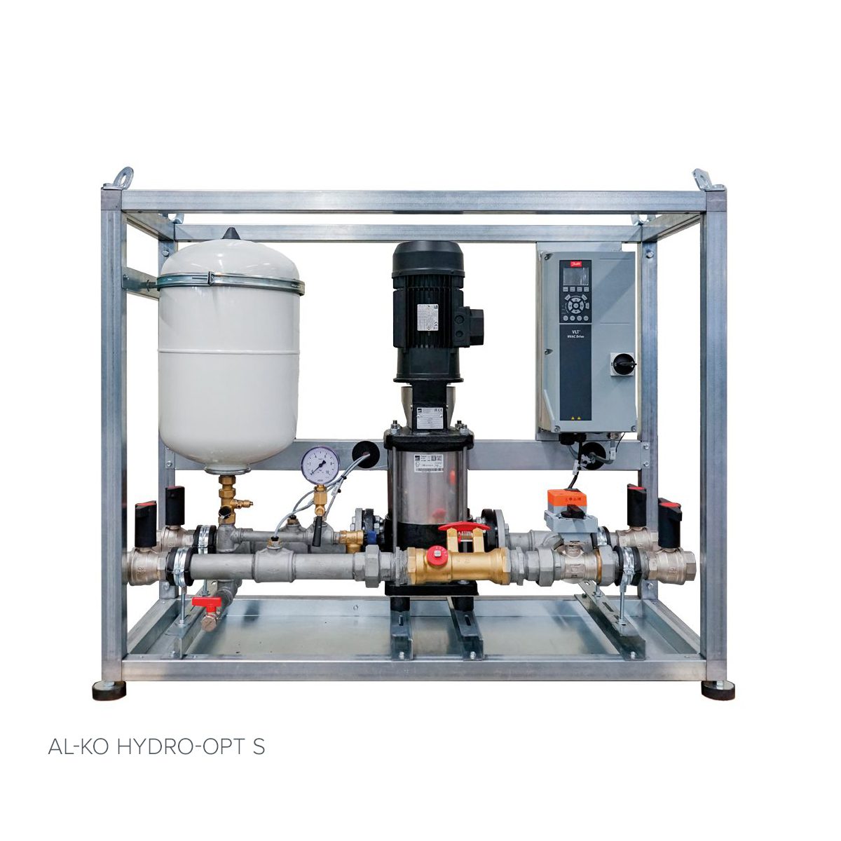
AL-KO HYDRO-OPT® S
| Type | Dimension | Flow in m3/h | Length in mm | Width in mm | Height in mm | Weight in kg |
|---|---|---|---|---|---|---|
| 0.5 | DN 20 | 0.35 – 0.55 | 1178 | 489 | 971 | 105 |
| 1.5 | DN 25 | 0.56 – 1.50 | 1178 | 489 | 971 | 110 |
| 3.5 | DN 32 | 1.51 – 3.50 | 1178 | 489 | 971 | 119 |
| 6.5 | DN 40 | 3.51 – 6.50 | 1178 | 489 | 971 | 133 |
| 11 | DN 50 | 6.51 – 11.00 | 1178 | 489 | 971 | 153 |
All specifications are approximate values, based on the basic version. Subject to technical changes.
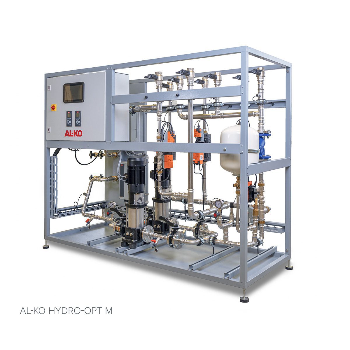
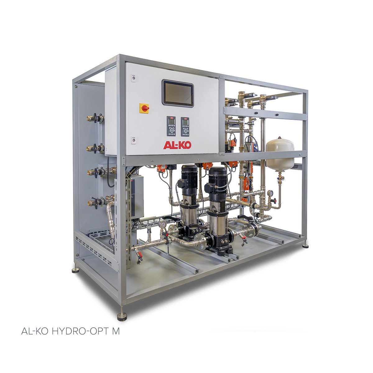
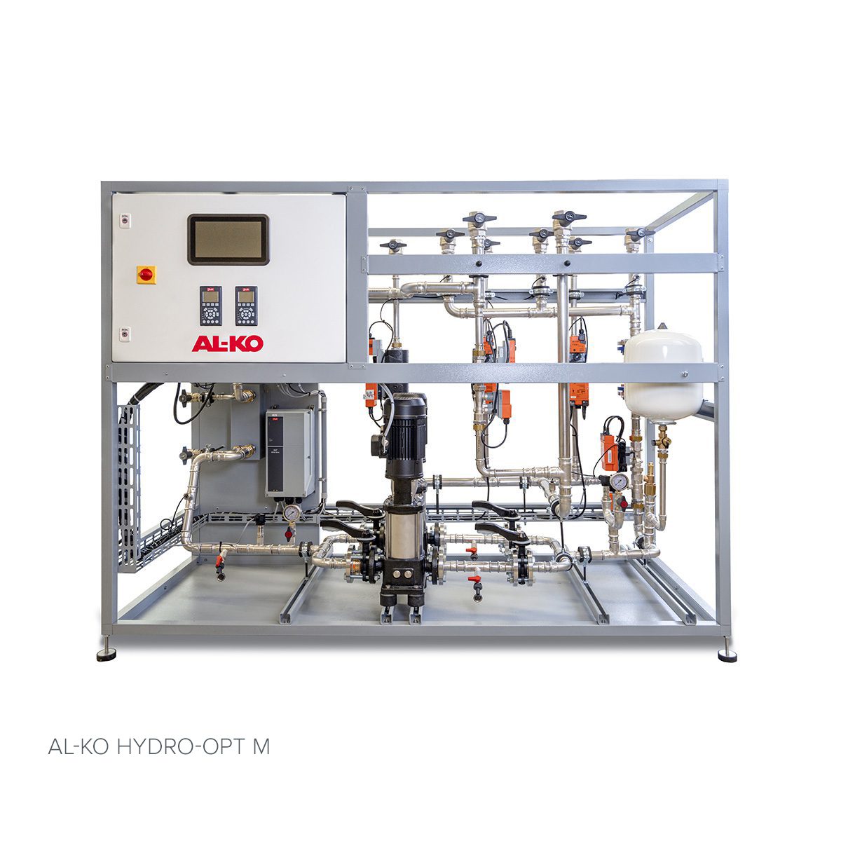
AL-KO HYDRO-OPT® M - 1 Air Supply Unit + 1 Air Exhaust Unit
| Type | Dimension | Flow in m3/h | Length in mm | Width in mm | Height in mm | Weight in kg |
|---|---|---|---|---|---|---|
| 2 | DN 32 | 0.5 - 1.9 | 1989 | 842 | 1454 | approx. 279 |
| 5 | DN 40 | 2.0 - 4.9 | 2142 | 842 | 1607 | approx. 328 |
| 10 | DN 50 | 5.0 - 9.9 | 2142 | 995 | 1760 | approx. 390 |
| 15 | DN 65 | 10.0 - 14.9 | 2525 | 1224 | 2142 | approx. 589 |
| 25 | DN 80 | 15.0 - 25.0 | 2678 | 1683 | 2525 | approx. 844 |
All specifications are approximate values, based on the basic version. Subject to technical changes.
AL-KO HYDRO-OPT® M - 1 Air Supply Unit + 2 Air Exhaust Units
| Type | Dimension | Flow in m3/h | Length in mm | Width in mm | Height in mm | Weight in kg |
|---|---|---|---|---|---|---|
| 2 | DN 32 | 0.5 - 1.9 | 1760 | 842 | 1454 | approx. 285 |
| 5 | DN 40 | 2.0 - 4.9 | 1760 | 842 | 1607 | approx. 338 |
| 10 | DN 50 | 5.0 - 9.9 | 1913 | 995 | 1760 | approx. 406 |
| 15 | DN 65 | 10.0 - 14.9 | 2219 | 1224 | 2142 | approx. 618 |
| 25 | DN 80 | 15.0 - 25.0 | 2372 | 1683 | 2525 | approx. 884 |
All specifications are approximate values, based on the basic version. Subject to technical changes.
AL-KO HYDRO-OPT® M - 1 Air Supply Unit + 3 Air Exhaust Units
| Type | Dimension | Flow in m3/h | Length in mm | Width in mm | Height in mm | Weight in kg |
|---|---|---|---|---|---|---|
| 2 | DN 32 | 0.5 - 1.9 | 1989 | 842 | 1454 | approx. 285 |
| 5 | DN 40 | 2.0 - 4.9 | 2142 | 842 | 1607 | approx. 363 |
| 10 | DN 50 | 5.0 - 9.9 | 2142 | 995 | 1760 | approx. 434 |
| 15 | DN 65 | 10.0 - 14.9 | 2525 | 1224 | 2142 | approx. 663 |
| 25 | DN 80 | 15.0 - 25.0 | 2678 | 1683 | 2525 | approx. 939 |
All specifications are approximate values, based on the basic version. Subject to technical changes.